- All plenums to be made from SMACNA rated sheet metal specifications.
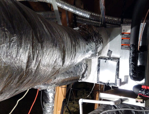
- Supply air plenum to be insulated with #2 density internal Fiberglass
- All other plenums to be insulated with #1.5 density Fiberglass.
- All plenums to be installed with sheet metal screws and sealed with UL181 mastic sealer on all seams.
- Furnace is to be hung from the rafters with 1″ channel strut. The strut is to be hung with 1″ wide solid sheet metal strap and secured with 1″ screws.
- The furnace is to be installed higher than the coil and the coil is to be installed with 2 2x4s lengthwise in top of the strut.
- The plenum on both sides of the coil will have an access door installed on both sides for servicing.
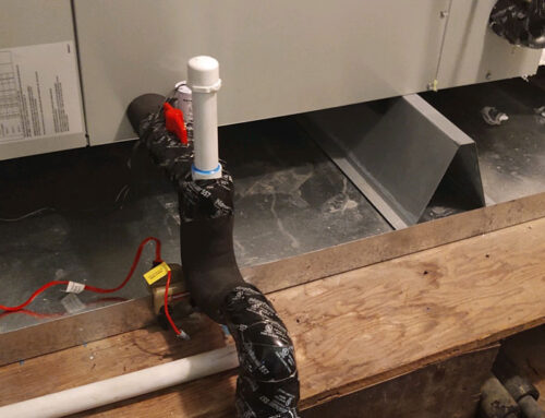
- The drain line will be installed with schedule 40 PVC and installed with a tee for added chemicals.
- There will be a shut off valve between the tee and coil to allow the coil to be isolated when the drain is flushed.
- The coil will be slanted toward the drain. The drain line will be secured to the floor to prevent breakage.
- The furnace will be installed with a flexible gas line.
- The furnace will have an optional 5″ pleated filter installed behind the furnace. This is to increase the air filtration to maximize efficiency.
- The plenum and coil will be strapped with 1″ strap for support.
- All ductwork will be sealed at the joints and secured with 1″ strap and insulated with 2″ foil-backed Fiberglass. This will be installed on the exterior of the ductwork and stapled to secure it to the ducts.
- The supply air plenum will have a balancing damper installed at all plenum supply duct connections. This damper will have a sealed shaft that is air tight with a raised 2″ platform adjustment. This adjustment shows the position of the damper and has a locking screw to secure the damper where it will not move once set in place.
- The refrigerant line will be properly sized for the system. The insulation on the suction line will be 2″ black foam insulation. All exposed insulation will be wrapped with UL181 foil tape to prevent deterioration from exposure.
- The overflow pan will be a heavy duty installed with schedule 40 PVC. The drain will be secured and installed to code requirements.
- All joints soldered will be done with 15% silver solder. (This is the standard for the highest quality solder)
- All hard sheet metal supply ductwork to be sized at 7pp feet per minute velocity. The ducts are to be sized aggressively at 20% safety factor for future balancing of the system
- All return ductwork to be installed with one floor return and one ceiling return per 500 square feet wherever possible. Where multiple returns are used, hard sheet metal ductwork will be installed with isolation boxes to minimize noise air return
- All ductwork will be installed as high as possible to make access to areas of the attic easier for service and storage
- Where duct systems used are flex, duct will be sized to a maximum of 600 feet per minute velocity. Secondary plenums will be used with a hard duct supply sized at 1000 feet per minute velocity, transferring the supply air to distribution through 2 plenums to minimize duct exposure to the attic elements
- Flex duct to be installed to maximum secure and strait installations
- Thermostats used will be electronic digital for more accurate control
- All supply grills to be white aluminum, factory painted, adjustable louvered grills.
- All return air grills to be aluminum. Ceiling grills to be square openings for minimum resistance
This design will incorporate several unique features that no other company will offer or agree with. It does not make it wrong to be different, but it attracts criticism. These applications are our way of addressing your exact needs. They are based on the house design. We look at each application and design the system to meet the needs of the home and the homeowner. This is not the norm as the business has been transformed into a commodity with little concerns to specific demands. We are not installing an air conditioning system; we are designing a “Life Support Breathing Apparatus.”

